Wednesday, 3 July 2013

Sewer Network Capacity Analysis Part 4

This post follows on from the previous one on creating catchments and exporting to SSA.

This post on Storm & Sanitary Analysis (SSA) makes use of the Modified Rational Method (Wallingford Procedure) and applies only to users in Ireland, the UK and anywhere else that uses this method.

SSA itself was originally called StormNET which was developed by a US based company called BOSS International. Autodesk purchased this package from BOSS about 3 years ago and included it with Civil 3D as an additional download in 2011 and as part of the main installation in subsequent years. Apparently it is a very comprehensive piece of software that sells for about $1100 per seat starting price on its own in the US.

Given that a different method of hydrologic analysis is used in this part of the world than in the US a lot of the functionality in the software is unusable here. When Autodesk purchased SSA some customisation for the Irish & UK market was undertaken which opened up a certain amount of the software's capability to users here. This post will cover what those functions are and also (some of) the limitations.

When you select Modified Rational Method as the hydrology type in SSA you can:
  • Calculate Greenfield runoff rate for the site (can use the catchment info imported with your pipe network from C3D).
  • Based on the greenfield runoff rate you can calculate the SUDS storage volume required.
  • You can run a storm event through your network and get SSA to upsize the pipes if necessary.
  • You can specify a storm event to check for surcharging in the pipes.
  • You can run analysis for circular pipes only (no open channels).
In the context of the analysis type discussed in this post (capacity check) it will tell you if a pipe is surcharged. What it doesn't tell you is if the extra flow could be accommodated for by storage in the structures. Since it can't calculate for storage in the structures it also can't determine if there is ponding at the structures. This is a serious limitation when it comes to this type of analysis.

So where is the software headed? Are we likely to see this functionality added for the modified rational method (MRM)? (the software can calculate for storage at the structures and ponding for the other hydrology methods as well as a whole array of other drainage design requirements just not for modified rational). It is hard to say whether this functionality of the software will be modified and opened up or here. There hasn't been any extra development in the software for the MRM for the last two releases (2013 & 2014). That would indicate that development has been put on hold so your guess is as good mine where it is heading. It is an obvious hole in the Infrastructure Design Suites offering at present. I imagine part of the plan of moving to suites rather than standalone products is so that Autodesk can offer a full design workflow and not have to provide export/import compatibility to third party software such as WinDes. I would think that given such a small market use the MRM the development of SSA to accommodate this is not too high up the priority list at Autodesk. Especially since it provides full functionality for other regions. Maybe if someone from Autodesk is reading this they can give some insight to what the future holds....

That said what it does, it does well and is easy to use. The fact that you can essentially do your 3D pipe network drafting in C3D and then export this to SSA ready for analysis makes for a smooth workflow. My own feeling is that if you are currently using an excel sheet for drainage design then you will save yourself hours and probably days of manual effort transferring invert levels and pipe sizes from excel to CAD and drafting up the result - especially when changes occur. (once the analysis is complete in SSA you can export back to C3D and it will update your pipe network for you - in plan and profile). I have spent my fair share of time designing pipe networks using excel sheets to know what is to be gained using C3D and SSA. Those excel sheets to be fair also probably contained errors given how many times they were handed down inside in an office but that is a different matter! If you are currently using WinDes with all the bells and whistles then this isn't going to be up to scratch - but those bells and whistles are expensive! For those who are using WinDes I would also consider using C3D as your pipe network drafting tool. You can lay out and display pipe networks both in plan and profile as well as extract setting out info and tables extremely fast once you have got your head around the commands. There is an export to WinDes tool to send the pipe network out for analysis and import from WinDes tool to bring back in the results. Hopefully we will see some future development from Autodesk for this part of the world!

Next post we will run through a workflow to complete the sewer capacity check in SSA...

Tuesday, 2 July 2013

Sewer Network Capacity Analysis Part 3

This post follows on from the previous one on Creating Pipe Networks.

Creating Catchments
Before we export our pipe network to SSA for analysis we need to define our catchments.

You can do this by first creating polylines to define each catchment. Follow the approach outlined in the previous post of using the surface slope arrows and the kerb lines to determine what sections of surface drain to each structure. Once you have polylines drawn you can turn them into catchments

In the Prospector tab of Toolspace right click on Catchments and select Create Catchment Group. Then right click on the catchment group and select Create Catchment from Object. Select a polyline and press enter to skip the flow path option. In the dialog box that follows we need to set four things:
  1. The catchment name - call this the same as the structure the catchment will flow to.
  2. The reference structure - use the box to the right to select structure from the drawing.
  3. The runoff coefficient - depends on the type of ground and will differ for the region or standard you are designing for but generally 0.9 for hard surfaces.
4. The Time of Concentration - On the Flow Path tab set the Calculation Method to User Defined. The TR55 option is a US based hydrology and doesn't apply here. The time will vary for the type of job you are working on but for a site like this 5 minutes would be sufficient. Enter the time in fraction of an hour - 0.083.

Repeat these steps for each catchment and you are then ready to export to SSA.
 
Export Pipe Network


On the Analyze tab of the ribbon select Edit in Storm & Sanitary Analysis
Select the pipe network and Ok. This will export to and open SSA.

Sewer Network Capacity Analysis Part 2

This post follows on from the previous one on drawing setup

Create Pipe Network
After the initial setup it is time to create your pipe network. There are two main options.

1. Create Pipe Network from Objects. This is usually a better choice for proposed networks where you may have drawn the initial pipe layout using a series of connected polylines. For a survey like this each pipe run will typically be a single polyline. When you use this command it will allow you only to select one object so you would end up with multiple (many, many multiple) pipe networks that would need to be merged together at the end into a complete network. This is a pain and it is best avoided.

2. Pipe Network Creation Tools. This opens up the pipes toolbar and will allow creation of multiple parts. You select the pipe and structure type and size and then start tracing over the survey polylines. This is a better option.When you are prompted, give your network a name and set the parts list. Do not set a reference surface as we do not want elements to try and correct themselves based on any surface information later.

What to Include in your Existing Network
Initially you may plan on recreating all elements of the surveyed network using C3D pipes. This is most likely unnecessary and will probably cause you problems.  See below:
Based on the surface slope arrows and also the layout of the kerbs and gullies I can determine the catchment for a particular structure (Blue Polyline). This structure has 6 gully connections all of which feed from the same catchment. The total flow for the catchment is assigned to the structure and it is not necessary to subdivide the catchment into flow for each gully. Therefore there is no benefit to modelling gully connections as C3D pipes. This will reduce the number of pipes and structures in your network.

Drafting the Pipe Network
The plan here is to use the pipes toolbar to trace over the main elements in your network and recreate the pipes and structures. We will forget about invert levels and cover levels when laying out the network and return to these afterwards.
Use the pipes and structures command above, start to layout your network by clicking at each structure location. The default drafting direction will be downstream  so try to work this way - otherwise you may get warnings when you try to analyse in SSA later.

Editing Invert & Cover Levels
Once you have recreated the main elements of your network we can then inspect the survey elements to determine the actual invert & cover levels of the pipes and structures and apply these to our network elements.

There are two main ways of getting this info from the survey elements:

  1. Use the 'ID' command (type at command line) and click on the ends of the pipe polylines to get invert levels.
  2. Use the text at the structures to determine cover and invert.
Using ID for each polyline is the most thorough and accurate approach. An (quicker and less accurate) alternative is to use the invert level of the structures as the invert level of the incoming and outgoing pipes - and assume they are they same. This is a lot quicker and may not make that much difference to the overall capacity analysis. Whatever approach you decide to use you will need to make note of the invert levels of the pipes and structures and then apply these to the C3D elements.


The best way to manually add this info is to select a structure and click on Structure Properties on the ribbon. On the Connected Parts tab you can edit the invert levels of the incoming and outgoing pipes first.


Next move to the Part Properties tab and set the Automatic Surface Adjustment to False - you can then enter the cover level (Rim elevation). Set the Control Sump Depth By property to Elevation and enter the structure invert level (Sump Elevation).

Click Apply and ensure that the values you enter hold. If they change then check to make sure that the structure invert level isn't higher then the lowest connected pipe invert. If this is ok then maybe look at the type of structure you are using. Sometimes there will be minimum dimensions for the structure elements and these may affect the manually entered invert levels - an you may need to use a different structure type.


This process is repeated for the entire network. It is important to ensure that you have the network as correct as possible at this stage before you export to SSA or you will be presented with a series of errors when you run the analysis.

Common things to look out for are that the correct number of pipes are connected to a structure and that they are sloping the correct way.
In the connected parts tab you can identify what pipes are coming into a structure (should be IN and have positive slope) and those which are going out (should be OUT and have negative slope. If these look wrong then check invert levels before exporting.

Another common issue at this stage is that a pipe is not connected to a structure. It may look like it is connected in plan but if it is not listed on the Connected Parts tab then it is not connected. You can fix this by selecting the pipe in plan and choose Connect Part on the ribbon and select the structure to connect.

If a pipe or structure is the incorrect type or size you can select it, right click and choose swap part and choose the correct one.

Next Post covers how to create catchments, and export to SSA.

Sewer Network Capacity Analysis Part 1

Following from some recent work the next few posts will cover how to create an exisiting storm sewer network in Civil 3D from survey data and then export the network to Storm & Sanitary Analysis (SSA) to check for capacity on the network. The SSA part will apply to users in Ireland and the UK only (or anywhere else that uses the modified rational method as the hydrology method).


Project Background
The survey consists of an AutoCAD drawing containing 3D polylines (pipe inverts) and blocks and text for manholes and data. Features such as kerbs, roads, banks etc are also included so a ground model can be generated.

This is the aerial image of the area with the site outlined in red.
There is a proposed new building for the greenfield area to the east of the existing building. It is proposed to connect the storm network from this proposed building into the existing network. The sewer capacity analysis is required to check first if the existing network can take the current flows and if so what capacity remains in the network and can it accommodate the new flows.

The survey drawing for the underground utilities will usually be 'crowded' - see below:
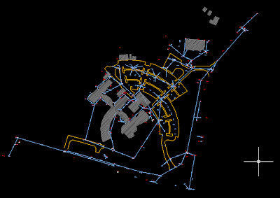
In this case we are only interested in the storm elements so this drawing can be made a lot simpler, see below.

Initial Drawing Setup

Generally the best first step is to copy and paste everything from your survey drawing into your C3D template - in my case I am using the AutoCAD Civil 3D UKIE.dwt.

Create your ground model from the survey drawing - see the following post if you are creating from CAD elements.

Isolate only the objects you need - so in this case I need anything to do with the storm network - pipes, manholes, text, gullies etc. Also isolate objects that affect the flow of water on the ground (kerb lines, buidlings etc) so we can determine catchments for the network. The drawing will be a lot simpler to read.

Set Pipe & Structure Catalog
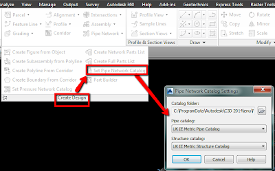
Next set the pipe and structure catalog to your localised settings. The catalogs are the highest level library of pipes and structures and contain all the elements that you can use in the drawing.

Create a Parts List
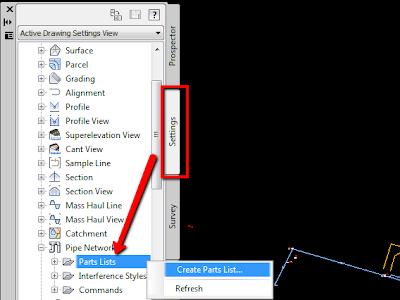
Next create a Parts List - this is a subset of the higher level catalog and will generally contain only the pipes and structures required for a particular type of network - eg Storm, Foul, Electrical ducting, water network etc. To create a parts list go to the Settings Tab of Toolspace and expand the Pipe Networks section. Right Click on Parts Lists and select Create Parts List. Give you Parts List a name.

Add Part Families & Sizes
The new parts list will initially be empty. We need to add in the pipe and structure types and sizes for our network. Still in the Create Parts List dialog box, browse to the Pipes tab. Right click on your network name and select 'add part family'.
Once added then right click on the family and choose 'add part size' Tick the sizes you need or the box to add all sizes.
Repeat these steps on the structures tab for the types and sizes you require.

Assign Rules & Styles
Apart from creating a smaller more manageable set of pipes and structures the other main use of the parts list is to assign styles (for plan, profile, section) and rules to your pipes.

The rules are more useful when laying out a proposed network and for this type of work we do not want to apply any rules. You can't turn rules off but you can create your own set of 'empty' rules. Still in the same dialog box click on the button to assign Rules and then create a new rule set. Do not add any rules and call the set something like _NO RULES.

Apply this rule set to the pipes.
For the styles select one that is appropriate for your needs. I like the Solid Centreline Schematic from the UKIE template. Follow similar steps for the structures, apply a NO RULES set and an appropriate style.

The next post covers drafting of the pipe network...