Showing posts with label volumes. Show all posts

Saturday, 12 October 2013

Not your Average Volume Calcs.

In some customised training recently I had a question on calculating the volume of material that was dumped on the side of an existing road. It turned out to be less straight forward than initially expected. The existing road is higher than the ground around it and original had a 2:1 embankment - that is all the information provided on the original condition. The fill material was dumped on top of this embankment. No survey existed for the original embankment so we had to somehow recreate the original ground level before we could calculate the volume of dumped material.

Belo is a screen shot of the current situation with a section through the fill to be quantified:
Manually drawn on one section below is the volume we need to calculate:
What we need to do is recreate the original field levels and road embankment at 1:1 to do our volume calculations - for simplicity we are going to assume the slope of the field continues in at the same grade towards the road:
 
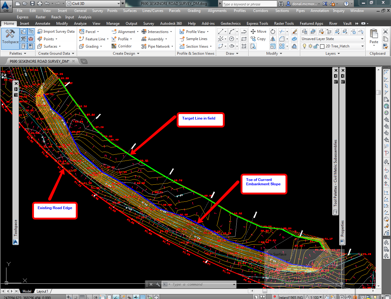
In plan below you can see the toe of current embankment - blue line. Red line is the road edge. 
To recreate the original field slope where the material was dumped we are going to use the overlaywidenmatchslope subassembly to build a corridor and get it to look at the existing field slope and continue this back in towards the road. Insertion point is toe of current slope and setting a target (green line) further out in the field will enable the assembly to calculate the slope of the field. 
The resulting corridor surface is shown below in purple. (actual slope may have been different but it is a good estimate). 
Next build another corridor with a linkslopetosurface subassembly. Alignment is existing road edge and existing profile. We will target the surface from the first corridor. 
The resulting corridor surface is shown below. We now have a good estimate of what the original ground levels were like before the material was dumped. 
Next to calculate the volumes we can define a material bounded by the three surfaces. 
 Volumes report below. 


Thursday, 18 April 2013

Quick Sports Pitch Design in Civil 3D

Below is a video that was created to demonstrate a workflow for designing sports pitches in Civil 3D.

The basic workflow is to create 3D linework (featurelines) to define the outline of the pitches, applying the proposed levels at the corners as we create them. The grading of the pitches was at either 1/100 or 1/140 and we can apply this as we create the featurelines, grading tools weren't required. The boundary featureline is created by snapping to the existing ground surface along the site boundary line. (you can quickly do this by turning the boundary polyline into a featureline and get it to pick up the levels from the existing surface). We then simply added all these featurelines into a new surface to create our proposed surface.

The volumes were then balanced by raising or lowering the featurelines as necessary, keeping an eye on the numbers in the volumes dashboard until they are close.

Wednesday, 5 September 2012

Volume Calcs. from Sections

I was creating an as built Civil 3D model of a windfarm job and was asked to calculate a number of quantities. One was the volume of rock fill. This seemed straight forward - compare finished road surface against top of rock and you have your answer. The problem was that my finished road surface slopes down from road edge to top of rock and then batters back from there to meet existing ground. A straight comparison between the two would give incorrect volume, see below:
2012-09-05_0942
This includes the portion on the outermost batter. The volume we actually require is this:
2012-09-05_0943
To get this we need to create a new surface comprising the road edge featurelines and the featureline where the initial embankment intersects the top of rock. First lets look at my assembly… I am using a combination of generic subassembly (linkwidthandslope) and a conditional subassembly to model different conditions in cut/fill.
2012-09-05_1031_001
If you look at creating a surface from the featurelines generated by the corridor you see that all the individual linkwidthandslope subassemblies have a point code P2 and thus only one featureline I can choose (this would effectively give me the same result as choosing top links to create my surface).

You need to create unique point codes for each subassembly and thus unique featurelines to choose from for corridor surface.
Select the subassembly and change the Point Code  in Properties. Road edge here:
2012-09-04_1712
Then slope to rock:
2012-09-04_1716
Rebuild the corridor and in now corridor surfaces you should see some extra featurelines:
2012-09-04_1719_001
Now on cross sections you should be able to calculate the correct volume for rock fill by comparing this new surface with top of rock:
2012-09-05_0943

Monday, 30 April 2012

Maximising Geotechnical Data in AutoCAD Civil 3D

Last Friday we held a webinar with Keynetix, Autodesk’s AEC Industry Partner for Geotechnical software, showing how to produce geotechnical and geo-environmental drawings, models and cross-sections quickly and accurately in AutoCAD Civil 3D by using KeyHOLE. Here is a link to the webinar (the first few minutes are missing..). The Civil 3D content starts at 36min... enjoy...


http://www.screencast.com/t/WpVljO7y8

Tuesday, 24 April 2012

Windfarm Access Roads - Volumes Calculations


When calculating the earthworks volumes for the site there will usually be a number of subsurface layers that we will need to take into account. For example a typical site might consist of 3 layers; a peat layer overlying an intermediate layer of reusable material under which there is a rock layer. All of these will probably be intersected by your proposed access road surface at some point and volumes calculations will involve comparisons between two or more of these surfaces.
In calculating the volumes we will look at two methods; Volume Surfaces and Materials from Cross Sections. While using volume surfaces is a great method for calculating volumes I have found that using materials is more flexible. You define a material as the volume you wish to calculate. For example I might create a material called Volume of Rock Cut and define it using the access road proposed surface and the top of rock surface. Materials are particularly useful where you have more than two surfaces bounding your desired volume. It also allows you to generate a cumulative volumes report for each material on a per cross section basis.


Volumes to be Calculated:

1.   Volume of Peat to be Stripped from Site
This is straight forward. Create a volume surface using the existing ground surface as the base and bottom of peat surface as the comparison. Extract the border from your final corridor top surface to give you a polyline representing the extents of the works. Add this polyline to the volume surface as a boundary (This can be added from the Toolspace).

2.   Volume Of Rock Cut
This is the volume bounded by the top of rock and the access road proposed surfaces. Create a material (Sections menu<Compute Materials) using these two surfaces. Set the Quantity Type and the Conditions as below:
The conditions in this case are telling Civil 3D that we want everything above the formation surface and below the rock surface.

3.   Volume of Rock Fill
This is the volume bounded by the bottom of peat and access road proposed surfaces. Create a material using these materials. Conditions are everything Below the proposed surface and Above the peat surface. Quantity Type is Fill. See completed material below.
Volume Cut/Fill Rock Materials on Cross Sections:


4.   Volume Reusable Material Cut
Between the bottom of peat and top of rock layers on this project there was a layer of material that was deemed competent enough to be reused as fill elsewhere. The volume required in this case is bounded by three surfaces; Proposed surface, top of rock and bottom of peat.

Create another material as before adding in the three surfaces. The Conditions are everything below bottom of peat and above the other two surfaces, Quantity Type is Cut. See below:
Volume Reusable Material on Cross Sections:
Once you have your materials calculated you can generate a volume report – Sections menu<Generate Volume Report and select the report template you wish to use. This provides an easy to read cumulative volume report for each of the cross sections.