Wednesday, 21 December 2011

Free Civil 3D Training Material

There is a wealth of free training material out there for not only Civil 3D but a whole range of Autodesk software. This can take the form of youtube videos, workflows posted on blogs and even full downloadable courses complete with notes, videos and datasets. Sometimes the amount of information and number of sources can leave you wondering where to start. This post aims to distil these down to a couple of the better (free) sources. Both of these contain material that you can come back to time and again and find something new:


Autodesk Education Curriculum:
Aimed at 3rd level students, the education curriculum for Civil 3D is an excellent place for a beginner to start learning the software. (More experienced users will most definitely find at least a couple of chapters of new material!).

The material contains PDFs of the notes along with accompanying exercises and videos. The notes are written with the assumption that the end user has no prior Civil 3D experience and also makes no assumption of engineering knowledge either. What you get is series of well explained and practical Civil 3D topics that are broken down into manageable chunks - making it easy to dip into for a couple of hours and walk away with something you can use. Download from the following link:


You will also find other training material here for everything from Revit Architecture to 3Ds Max design. enjoy...

Autodesk University:
Without doubt one of the best resources out there for Civil 3D training material is the Autodesk University. Autodesk University is a conference held each year by Autodesk at which both Autodesk and industry experts present on their use of the software. These presentations along with handouts, powerpoints, datasets and any other files are available for download from the website at

http://au.autodesk.com/.

What I like about these presentations is that they are focussed on using the software to complete a particular task or design. For example there are some great classes on there for junction design and overlay design. The classes focus on what you need to know only, saving you the time figuring it out yourself. These are usually given by people who have been using the software for this purpose in real world situations. As a result they contain some great practical tips and solutions for the task at hand.

Users will need to create an account on the website and after that material is free.

Friday, 16 December 2011

Reference Two Surfaces on one Label

I had a query recently about how to display both proposed and existing surface levels on one label/location and at set intervals along your alignment.


The answer involves creating a label style which consists of reference text. Reference text is a hidden gem and can be very useful in all sorts of situations. Basically it is a component added to a label which reads information from another Civil 3D object and displays that information in the label for the current object.


So in our case we will create an alignment label that is going to reference the level from two different surfaces. The other types of Civil 3D objects that you can reference are alignments, cogo points, parcels and profiles so you can end up getting quite creative with your labels...


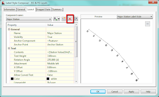
To start, select your alignment, right click and select Edit Alignment Labels. Make a copy of one of the existing label styles.


On the layout tab of the dialog box delete the existing components.


Now add a component as below and select Reference Text.


When asked for Type choose surface and give the component a name of 'EG Levels'.


Edit the text contents by clicking in the cell containing 'Label Text' and change this to reference Surface Elevation as shown below:


Repeat this adding another reference text component calling it FG Levels. In the text properties give this one a Y offset so the labels don't overlap.


Add the label to your alignment and set the increment as required. Now back in your drawing you should see something that looks like this:


The labels have been set up to reference a surface but we haven't told it which surface yet - this is why we see the question marks.


There is a bit of a trick to setting the referenced surfaces. If you click on a label it selects the whole set because that is what we have applied to the alignment - a label set. There is nowhere to set the reference objects in the label properties.


However, if you hold down control and click on a label it allows you to individually select a label and in the properties palette (right click and Properties) we can set the reference objects.


With a label selected click in the cell where it says <none> and move your cursor into the drawing, right click and select the surface from the list - do for both. Your label should now be referencing two surfaces.


To set the surfaces for the entire label set; select the label set, right click and isolate objects. Then hold down control and drag a selection box around all the labels, now in properties palette you can set the surfaces for all labels.


Just as an aside, the initial query I had was how to show proposed levels at the locations where the alignment crosses the existing contours. After much playing around I figured it wasn't possible without some programming but this was a suitable workaround.

Wednesday, 7 December 2011

Wind Farm Access Roads - Drainage Ditch Locations

Wind farm access road design often involves the placing of a drainage ditch on the uphill side of the road only. This appears to be a straight forward task but is complicated by the fact that this side can change as the access roads wind their way around the hilly terrain and there is no subassembly that can automatically achieve this.

You can display contours and slope arrows on a surface style to identify the areas where the uphill locations are in relation to your roads. This can be cumbersome, however, particularly if you are dealing with a large surface where performance is affected by the need to regenerate all those slope arrows.

The uphill side of the road can be identified more efficiently by using a combination of a temporary corridor and a volume surface.

First create an assembly using the generic subassembly 'linkoffsetandslope', setting a slope of 0% and offset from baseline to say 20m (wide enough from baseline to give a good indication of the lie of existing ground).


The assembly layout appears as below:


Next create a corridor using this assembly, the access road alignment and vertical design for the access roads. Create a surface on this corridor using top links. Now create a volume surface (with 2D elevation banding style) using the existing ground as the base surface and the corridor surface as the comparison. In the surface properties on the analysis tab run an elevation analysis with one range and set the maximum elevation for this range to 0m.

In plan we can easily identify the uphill side of the road along our access roads.


In this case green areas identifying the sides of the alignment where we need ditches need to be applied. We can now split our design corridor at these locations and apply subassemblies with drainage on the correct side to each region.

Wednesday, 30 November 2011

Adjusting Alignment Chainage and Sample Line Behaviour

What happens if you extend the start of an alignment after you have created sample lines and sections?

Say the alignment at the beginning of the scheme was required to be extended by 20m - the section originally at chainage 0m now is at chainage 20m - this might be a problem particularly if drawings had already been issued with the sections at the original chainages. By default the sample lines and hence the sections are locked to the alignment and will adjust to suit the edited alignment. See screen grabs below.

Alignment original chainage and sample lines


Alignment new chainage and sample lines


You can unlock the sample lines from the alignment which will get around this issue. Select one of the sample lines in plan, right click and select similar, right click again and select properties. You can unlock the sample lines here by setting the value to FALSE.


However, this means that any changes to the alignment horizontal geometry will not be reflected in the sections and so you may still want the sections to be locked to the alignment but hold their original chainage. What we need to do is modify the alignment reference point.

Keep your sections locked to the alignment, extend the alignment start chainage by the desired value. Select the alignment and in alignment properties on the Station Control tab click the button to set the reference point for the alignment making sure that the Station is set to zero and pick the start of the original alignment in your drawing. See below:


Now we have an extended alignment but with sections at the original chainages that are still linked to the alignment should we need to make changes later!