Tuesday 28 February 2012

Creating Custom Point Properties

This week I was presented with survey data in ASCII point file format that contained numerous attributes for each point. For example a point might have a description of 'spot height' and also another attribute denoting ground type at the same point.


Initially I thought it wasn't possible to get this extra information into Civil 3D in a usable format until I discovered the 'User Defined Property Classifications'. (Toolspace<Settings tab<Points). Right click and select Create New.


Next right click on the new classification and select to create new user defined property. Here we create the property that will accept the attribute from the survey data. In my case I am creating a Ground Type property. Set the property field type to suit the attribute type in the point file - in my case string (text). 


Once we have created our user defined property we need to add this to a new point file format to match the point file. Toolspace<Settings tab<right click on Point File Formats and select new. Select User Point file.


Give the new format a name, set the default file extension and set other options as necessary. Click on each of the column headers where it reads <unused> and select the appropriate column name. In my case P,E,N,Z,D and finally my user defined property 'Ground Type'.


To test click Load at the bottom of the dialog box and load in a test file, click on Parse and the values from the point file should populate the columns as below.


Now we can import our point file using the new point file format...


Once the points are imported we can then use the custom property to add information to point labels. Select a point, choose Edit Label Text from the ribbon. You can select your custom property to add to the label as shown below.


You can also use the custom property to populate point groups... Create a new point group (in this case I am creating a point group for Soft Ground points only). In the PG properties on the Query Builder tab you can build a query as below to add the points of a particular ground type to the point group. 


There are probably plenty of more uses for these user defined properties. Please post if you have any suggestions...

Monday 20 February 2012

Setting Out Points Along Land Take Line

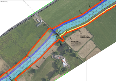
In the screen grab below we see part of a 15km proposed new canal design. The thick orange line is the land take line along which a fence needs to be erected. We need to create points along this line at 15m intervals and then export these out to csv file for upload to our GPS logger for setting out. Needless to say you don't want to be manually specifying each point location so the following is a workflow for speeding up the process.


We will use the point creation tools to create the points but before we do we will modify the command settings so that we are not prompted to enter a description for each point. In the Settings tab of toolspace expand points<Commands and right click on CreatePoints and select edit command settings. Here we change the settings as below to enter a default point description of FENCE SETOUT and set the prompt value to Automatic. In my case I have set the prompt for elevations to Automatic also which will pick up the level of the chosen surface but this may not be needed.


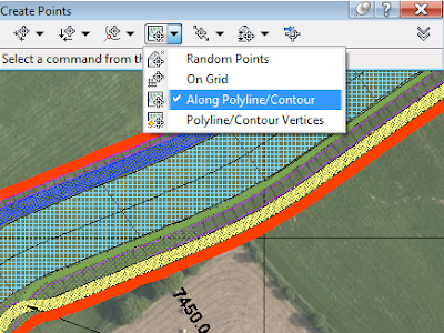
Next go to Points on the Home ribbon and select point creation tools. On the Create Points toolbar select Along Polyline/Contour as below. 


Select your surface if prompted/ needed. Specify distance between points and then select the polyline representing the fence. This will create points along the polyline with the default description.

Next to get these points out to a point file to import into your logger you can create a new point group and export this.

On the Prospector tab of toolspace right click on Point Groups and select new. Give the point group a name and set the point and label styles.


On the Include tab tick the box beside With Raw Descriptions Matching and enter the point description. This will dump all your fence set out points into one point group giving us easier control over them.


Now to export to point file, right click on the point group name and select export.


Choose the point file format and specify destination (you specify file type (csv, txt, xls) here also. Tick the box to limit to a point group and click ok. 


This will get your fence setout points to a file format that can easily be uploaded to logger for set out.

Monday 13 February 2012

Civil 3D Point File Coordinate Conversion

Its not uncommon to have a drawing which is at one coordinate system and for the same project to have a survey that was undertaken to a different coordinate system. You need to import the point file from the survey into C3D so that it appears at the coordinate system of the drawing.


Firstly you may have already seen the tick box in the import points dialog box to 'Do coordinate transformation if possible' (see image). Just ticking the box will have no effect without a bit of setting up first. This is where the 'if possible' bit comes into play. In order for C3D to perform the transformation it needs to have a coordinate system defined in both the drawing and on the imported point file. When you import points and tick this box C3D will transform the points to the coordinate system of the drawing.
Assigning the coord sys to the drawing is straight forward. Type MAPCSASSIGN at the command line and select. In my case for Ireland the drawing is to ITM. You can use the filters here to help you search.
Next we need to define the second coordinate system on a new point file format which we will then use to import the point file.

First open the import points dialog - click on points menu<Import/Export points<Import points.
In this dialog box click on the icon in the image below to create a new point file format.This is made easier by making acopy of one that already matches the format of the point file you are going to import.
In the point file format dialog box set your default file extension and the coordinate system of the point file. The next bit is very important... you must make sure that that the columns for easting and northing are set to Grid Easting and Grid Northing otherwise the conversion will not work and cue hours of frustration!
With the point file format set up and back in the import points dialog box browse to your point file, selct the point file format just created and then tick the box to do coord transform and that should be it!


Monday 6 February 2012

Copying Superelevation Data Between Alignments


In order to get C3D to automatically apply superelevation (SE) from the design criteria file you will need to have properly defined geometry on your horizontal alignment. That is to say that Civil 3D needs to see transitions and curves on the alignment to automatically apply the SE.


If you are using a surveyed road centreline (for overlay jobs for example) to define your alignment geometry you will probably not have defined curves and transitions on your alignment. This will be usually be the case if you create the alignment from a polyline. The polyline connecting the surveyed points consists of a series of straights. While we might know by looking at the alignment where a curve exists, Civil 3D only sees a series of short straights joining the points and will not be able to apply SE automatically from the design criteria file.


You can add it manually using the SE curve manager. To do this select the alignment and click on Superelevation on the ribbon< Calculate/Edit Superelevation < Open the Superelevation Curve Manager. Here you can manually add SE data. You will need to enter data for each curve and transition manually however which is cumbersome.


An easier way to do this is to create a best fit alignment from your surveyed road centreline, apply SE automatically to this alignment and then copy these values and paste them onto the actual road centreline alignment.


First create an alignment from the surveyed road centreline polyline as before. Then use the create best fit alignment tool to create an alignment from the same polyline. Your best fit alignment will have curves and transitions which you can tweak to match the existing road alignment. You can then apply superlevation to the best fit alignment as you normally would. (Select the alignemnt and click on Superelevation on the ribbon< Calculate/Edit Superelevation < Calculate Superelevation now).


If you then open up the SE tabular editor for the best fit alignment there is a new command (see below) in 2012 that allows you to export SE values to excel file.


Export the SE values from the best fit alignment. Open the tabular editor for the surveyed road centreline alignment and click import. We then have SE values applied to our surveyed road centreline for the existing horizontal geometry.