Sunday, 29 January 2012

Junction Upgrade in Civil 3D


This post outlines a workflow for upgrading an existing junction using Civil 3D. The incoming and outgoing lanes of the junction are to be widened to accommodate HGV movements while maintaing the existing main road crossfall along the widened portion.

First lets take a look at the existing junction...


First create centreline alignments for both roads and create surface profiles for each sampling existing ground. Next use the junction design wizard to create our proposed curb return and offset alignments. We are only going to use the horizontal curb return geometry created by the wizard – untick the options to create curb return and offset alignment profiles... 


...and also the option to create the corridor.


A warning message appears to inform us that we are using dynamic surface profiles. Continue with the dynamic profiles.


The wizard creates offset and curb return alignments...


The curb return alignments rely on the offset alignments for their geometry. In order to be able to edit and stretch the curb returns to suit our design we will first have to stretch out the offset alignments to give ourselves enough room to work with.
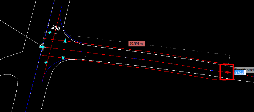

This needs to be completed for both roads. Next we add turn in lanes to the junction to model the widenings. Select the junction marker and select edit curb returns from the ribbon. Tick to add widen lane for each of the incoming lanes for both curb returns.


Completed curb returns below:


Next we need to extend out the existing main road cross fall so that we can determine the levels along the widened curb return alignments. To do this we create a temporary corridor using the widenmatchslope subassembly. This will allow us to target the existing road surface at the crown and existing road edge and then continue this slope out wide enough to extend past the new widened section - giving us our proposed levels along the widened alignments.

First create the assembly:


The assembly properties are set as below:


Most of the values are set to zero - we are going to use corridor targets for the insert and sample points. We are not overlaying the existing road and we are not adding a widen lane with this assembly so these values are set to zero. The only value we set is the width for the widen portion, this is set at a value that will be wide enough to cover the widened area. Setting a number of values to zero like this will result in a strange looking layout assembly. The appearance of this is not important, it is the behaviour we are interested in.


Create a temporary corridor using this assembly, the main road centreline alignment and existing profile. In the target mapping set the insert point as the edge of existing road and the sample point as the existing road centreline for both the width and offset targets. Also target the existing ground surface.


The temporary corridor can be seen below:


Now create a surface on this corridor and set style to all off. To ensure that our corridor is extending the existing road cross fall correctly we can project the corridor surface onto our side road profile and check as below:


We then create a profile along each of the curb return alignments sampling both the existing ground and temporary corridor surfaces. This should look something similar to below:


We can see the existing ground surface profile in green and the corridor surface in purple. We need to manually draw our design profile using these as a guide. On the left in the profile above we can see where the NE curb return is running along the edge of the main road. The existing road surface is blank for a portion where we are outside the extents of the survey and then on the right we see where we are tying back into the side road. When drawing our design profile we can trace over the temporary corridor surface and tie back into the existing ground at the end of the curb return on the side road. See below:


Repeat this process for the SE curb return. Next we create a curb return assembly.


This will need to contain a subassembly with the ability to target horizontally and vertically. We then build our junction corridor using the curb return alignments as the baselines. The first pass of the NE curb return corridor below:


We need to set two corridor targets - the existing main road edge (surveyed 3D polyline) and the side road alignment and profile

These two targets can be added together - the default behaviour is that Civil 3D looks for the nearest one. Set these for both the horizontal and vertical targets.


Complete the SE curb return in the same manner and the finished corridor appears as below:

Found this useful? Need to learn more? Check out our Advanced Junction Design course HERE

Thursday, 12 January 2012

Connecting to MapInfo files in Civil 3D & Map 3D


There are a couple of ways of connecting to MapInfo data in Civil and Map 3D... 
  1. Use the MAPIMPORT command
  2. Download the free FME FDO provider to allow connectivity to MapInfo files through the standard Map and Civil 3D FDO

We will explore both methods here and also look at the pros and cons of both.

1.  Using the MAPIMPORT command.

On the command line type MAPIMPORT. Browse to the data files and change the files of type to suit.


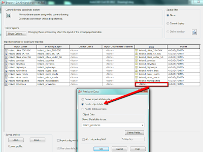
Select the files and click OK. In the import dialog box for each layer under the data column, click where it reads none and select to create object data - this will add the object data present in the MapInfo files as attributes to the AutoCAD objects (tip here to create polylines instead of mpolygons is to set the MAPUSEMPOLYGON variable to OFF) created on import.

After importing the data we can inspect the properties of the imported objects. Below we see that the selected polyline has been placed on an AutoCAD layer with the same name as the MapInfo file it was imported from. Also we can see that the object data has been added as an attribute to the polyline - the province name in this case.


The data is imported in AutoCAD format. The control of the display of the imported objects is achieved through use of AutoCAD commands - layers, draw order etc... as you would with any AutoCAD objects. We cannot perform any GIS analysis on the data - for example to stylize or query the objects based on the attached attribute data. In summary importing using the MAPIMORT command is useful to create AutoCAD drawings from the MapInfo files but leaves us limited in terms on controlling the display of and analysing the data.

Using the FDO connection provides us with more control over the data...


2.    Use the FDO data connect

The out of the box FDO in Map and Civil 3D does not allow connectivity to MapInfo files. Luckily there is a add-on that will enable connection to 9 additional formats including MapInfo TAB, MIF/MID and SPATIALWARE...


The add-on, developed by Safe Software, is free and can be downloaded from the following link:


Once installed you can access the new connections through the FDO in Map or Civil 3D. On the command line type MAPWSPACE and press enter twice. This brings up the Map workspace. Click on DATA icon and connect to data...


...here you will see the usual data connection formats plus an extra one entitled Add FME connection. Double click on this and select MapInfo Tab as the file format. Browse to the files, select and open.


Back in the data connect dialog box select the tick boxes to display the schema and click on Add to Map


The selected files are added as Map 3D layers to the drawing... 


...this allows you to control the draw order easily through Map task pane by dragging and dropping layers to change their order.


You can also easily control the display of layers by checking or unchecking the tick box beside each.


You an also view the object data associated with each layer in table format. In the table you quickly zoom to a particular feature by right clicking on one and selecting zoom to.


You can use the style button to control and edit the display of each layer. We can make use of the information in the data table to enhance layer appearance. For example in this case I have imported a MapInfo file containing elevations. We can edit the style of this layer to show ranges in elevation and give more depth to our drawing.


To do this, first change the draw order of the layers to bring the layer you are going to stylise to the top. Highlight the layer in the Map Workspace and click on style, select new theme and choose the property upon which you wish to stylize the layer. Then change the colour of the style range to suit.


Once this is complete the layer style will update automatically in the drawing.


In summary using the FDO data connect in Map and Civil 3D provides you with far greater control over the data than using MAPIMPORT, for both display and GIS analsyses.

Friday, 6 January 2012

Customising Cross Sections


A query that has come up regularly (on overlay jobs) is how to display proposed levels on cross sections at specified offsets from the baseline... (and then get them out to csv file)


For this example I am using the UKIE country kit:


First add a new band to your cross section in the section view properties < bands tab - Select the 'Surface Levels at Major Interval (Section 1)' band style from the list as shown and click 'Add'.


Untick 'Match major/minor increments to vertical grid intervals'. Set the 'major interval' for your band to the desired offset. The display of the minor interval labels is turned off by default for this band.


Set the band to read the desired surface and your sections should display levels at offsets from baseline.


While it is one thing to have these levels displayed on cross sections; how do we get them out to csv file for setting out? This takes a bit more working around. There may be an easier way to achieve the following so please post it if you know how...


Create your final corridor with finished ground surface. Create a new assembly. On the 'Generic' tab of the toolpalettes select the 'LinkOffsetonSurface' subassembly and set the following properties:


Offset from Baseline: 2.5m
Point Codes: 2.5m right


Leave other options at default. Build a new (dummy) corridor using this assembly, the road centreline alignment and associated profile. In the corridor properties < parameters tab < set all targets and set the target surface to the surface you want to sample.


Now we can extract the points using reports. In your Toolspace under:  Toolbox tab < Reports Manager < Corridor < use the 'Section Points Report'


In the report dialog box select your dummy corridor (the linkoffsetonsurface one) and you should see your point code listed under the list of features. Set the station interval and click create report. You can then copy from here into excel and edit as necessary.


There are other reports in the toolbox that will produce something similar but i have found this one easiest to edit in excel afterwards. Also as an alternative you could create cogo points from your dummy corridor, place them in a point group and export them directly to csv file. Using the report above produces a better result as it will give points across your corridor at each chainage. Exporting from point group only gives easting northing and not chainage.


Also why not add the linkoffsetonsurface subassembly to your design corridor assembly rather than creating a new assembly for it?


If you add the linkoffsetonsurface subassembly to your design corridor assembly you cannot reference the corridor finished ground surface in the targets. This is because a circular reference will be created – both the corridor and the assembly would be trying to reference objetcs from eachother. The solution is to create a separate assembly as above.


I had originally posted this on the UK & Ireland Civil 3D user forum at http://civil3dukie.com

Wednesday, 21 December 2011

Free Civil 3D Training Material

There is a wealth of free training material out there for not only Civil 3D but a whole range of Autodesk software. This can take the form of youtube videos, workflows posted on blogs and even full downloadable courses complete with notes, videos and datasets. Sometimes the amount of information and number of sources can leave you wondering where to start. This post aims to distil these down to a couple of the better (free) sources. Both of these contain material that you can come back to time and again and find something new:


Autodesk Education Curriculum:
Aimed at 3rd level students, the education curriculum for Civil 3D is an excellent place for a beginner to start learning the software. (More experienced users will most definitely find at least a couple of chapters of new material!).

The material contains PDFs of the notes along with accompanying exercises and videos. The notes are written with the assumption that the end user has no prior Civil 3D experience and also makes no assumption of engineering knowledge either. What you get is series of well explained and practical Civil 3D topics that are broken down into manageable chunks - making it easy to dip into for a couple of hours and walk away with something you can use. Download from the following link:


You will also find other training material here for everything from Revit Architecture to 3Ds Max design. enjoy...

Autodesk University:
Without doubt one of the best resources out there for Civil 3D training material is the Autodesk University. Autodesk University is a conference held each year by Autodesk at which both Autodesk and industry experts present on their use of the software. These presentations along with handouts, powerpoints, datasets and any other files are available for download from the website at

http://au.autodesk.com/.

What I like about these presentations is that they are focussed on using the software to complete a particular task or design. For example there are some great classes on there for junction design and overlay design. The classes focus on what you need to know only, saving you the time figuring it out yourself. These are usually given by people who have been using the software for this purpose in real world situations. As a result they contain some great practical tips and solutions for the task at hand.

Users will need to create an account on the website and after that material is free.


Friday, 16 December 2011

Reference Two Surfaces on one Label

I had a query recently about how to display both proposed and existing surface levels on one label/location and at set intervals along your alignment.


The answer involves creating a label style which consists of reference text. Reference text is a hidden gem and can be very useful in all sorts of situations. Basically it is a component added to a label which reads information from another Civil 3D object and displays that information in the label for the current object.


So in our case we will create an alignment label that is going to reference the level from two different surfaces. The other types of Civil 3D objects that you can reference are alignments, cogo points, parcels and profiles so you can end up getting quite creative with your labels...


To start, select your alignment, right click and select Edit Alignment Labels. Make a copy of one of the existing label styles.


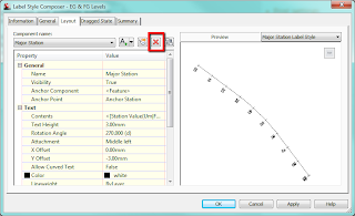
On the layout tab of the dialog box delete the existing components.


Now add a component as below and select Reference Text.


When asked for Type choose surface and give the component a name of 'EG Levels'.


Edit the text contents by clicking in the cell containing 'Label Text' and change this to reference Surface Elevation as shown below:


Repeat this adding another reference text component calling it FG Levels. In the text properties give this one a Y offset so the labels don't overlap.


Add the label to your alignment and set the increment as required. Now back in your drawing you should see something that looks like this:


The labels have been set up to reference a surface but we haven't told it which surface yet - this is why we see the question marks.


There is a bit of a trick to setting the referenced surfaces. If you click on a label it selects the whole set because that is what we have applied to the alignment - a label set. There is nowhere to set the reference objects in the label properties.


However, if you hold down control and click on a label it allows you to individually select a label and in the properties palette (right click and Properties) we can set the reference objects.


With a label selected click in the cell where it says <none> and move your cursor into the drawing, right click and select the surface from the list - do for both. Your label should now be referencing two surfaces.


To set the surfaces for the entire label set; select the label set, right click and isolate objects. Then hold down control and drag a selection box around all the labels, now in properties palette you can set the surfaces for all labels.


Just as an aside, the initial query I had was how to show proposed levels at the locations where the alignment crosses the existing contours. After much playing around I figured it wasn't possible without some programming but this was a suitable workaround.

Wednesday, 7 December 2011

Wind Farm Access Roads - Drainage Ditch Locations

Wind farm access road design often involves the placing of a drainage ditch on the uphill side of the road only. This appears to be a straight forward task but is complicated by the fact that this side can change as the access roads wind their way around the hilly terrain and there is no subassembly that can automatically achieve this.

You can display contours and slope arrows on a surface style to identify the areas where the uphill locations are in relation to your roads. This can be cumbersome, however, particularly if you are dealing with a large surface where performance is affected by the need to regenerate all those slope arrows.

The uphill side of the road can be identified more efficiently by using a combination of a temporary corridor and a volume surface.

First create an assembly using the generic subassembly 'linkoffsetandslope', setting a slope of 0% and offset from baseline to say 20m (wide enough from baseline to give a good indication of the lie of existing ground).


The assembly layout appears as below:


Next create a corridor using this assembly, the access road alignment and vertical design for the access roads. Create a surface on this corridor using top links. Now create a volume surface (with 2D elevation banding style) using the existing ground as the base surface and the corridor surface as the comparison. In the surface properties on the analysis tab run an elevation analysis with one range and set the maximum elevation for this range to 0m.

In plan we can easily identify the uphill side of the road along our access roads.


In this case green areas identifying the sides of the alignment where we need ditches need to be applied. We can now split our design corridor at these locations and apply subassemblies with drainage on the correct side to each region.

Wednesday, 30 November 2011

Adjusting Alignment Chainage and Sample Line Behaviour

What happens if you extend the start of an alignment after you have created sample lines and sections?

Say the alignment at the beginning of the scheme was required to be extended by 20m - the section originally at chainage 0m now is at chainage 20m - this might be a problem particularly if drawings had already been issued with the sections at the original chainages. By default the sample lines and hence the sections are locked to the alignment and will adjust to suit the edited alignment. See screen grabs below.

Alignment original chainage and sample lines


Alignment new chainage and sample lines


You can unlock the sample lines from the alignment which will get around this issue. Select one of the sample lines in plan, right click and select similar, right click again and select properties. You can unlock the sample lines here by setting the value to FALSE.


However, this means that any changes to the alignment horizontal geometry will not be reflected in the sections and so you may still want the sections to be locked to the alignment but hold their original chainage. What we need to do is modify the alignment reference point.

Keep your sections locked to the alignment, extend the alignment start chainage by the desired value. Select the alignment and in alignment properties on the Station Control tab click the button to set the reference point for the alignment making sure that the Station is set to zero and pick the start of the original alignment in your drawing. See below:


Now we have an extended alignment but with sections at the original chainages that are still linked to the alignment should we need to make changes later!