
Thursday, 29 November 2012
Install Student Version Direct from Browser
While installing the student version of C3D this morning I went to the student community website to download first and noticed that there was an option to install direct from the website. This removes the unnecessary steps of downloading and executable, then extracting and finally installing which altogether take some time. The install was complete in less than an hour and a half and was a lot less hassle than the more traditional download/install approach. Hopefully we will see this method of delivery rolled out for 2014 releases on commercial licences next year!


Thursday, 15 November 2012
AutoTrack - Wind Turbine Transport Vehicles
There are a couple of wind farm vehicles in the AutoTrack library. These are under Specialist Vehicles (Worldwide) category, see below:
 There are two types of vehicle - both have the same tractor component but have different trailers and loads. The first vehicle is a 24m long blade transporter and the second is a 50m long tower transporter with clamped trailer, see image above.
The vehicles are locked from editing by default. In order to modify these to suit your own requirements you will need to right click on the vehicle name and select edit a copy.

One of the features common to large vehicles such as these is secondary steering. This is where the axles on the trailers have their own steering. This secondary steering can be linked to the main steering (limits can be set on the amount of secondary steering) or it can be independent and controlled by the driver as he is turning. It may also be a combination of both of these and in that case you will want the option to have rear steering but be able to independently override this at time of turning.
To do this you will need to make a copy of the vehicle as mentioned above, then right click on it and select 'edit using advanced editor'. Highlight the trailer unit and click on 'edit'


The vehicles are locked from editing by default. In order to modify these to suit your own requirements you will need to right click on the vehicle name and select edit a copy.

One of the features common to large vehicles such as these is secondary steering. This is where the axles on the trailers have their own steering. This secondary steering can be linked to the main steering (limits can be set on the amount of secondary steering) or it can be independent and controlled by the driver as he is turning. It may also be a combination of both of these and in that case you will want the option to have rear steering but be able to independently override this at time of turning.
To do this you will need to make a copy of the vehicle as mentioned above, then right click on it and select 'edit using advanced editor'. Highlight the trailer unit and click on 'edit'

In the edit dialog box click on the 'Rear Axles' tab and then click on the 'Steering' button, then tick the box shown below and enter your max secondary steering angle and lock to lock time as shown below (these will be vehicle specific):

Now when you are 'driving' this vehicle in AutoTrack you can override the rear steering and independently control it as you are navigating your vehicle. To override you can click on the option below or use the wheel on your mouse.

Monday, 22 October 2012
Rotate Survey Point Levels to Align with String
When using the survey tools in Civil 3D there will likely be things that the software (or any software for that matter) appears to not be able to do at first glance. Digging a little deeper usually provides a solution or workaround. One of those cropped up today.


Can you automatically rotate survey point labels to match the orientation of the survey figure? The answer is... well no actually you can't as far as I am aware but there is a decent workaround that gives the same result.
After playing around with survey point settings I concluded that you couldn't rotate the label based on the orientation of the survey figure - you cant reference another object in the label settings. Likewise with the figure labels you couldn't reference the elevation of anything in the definition. Similarly nothing of use in creating a marker point label to label the vertices of the figure. The answer lay in regular line and curve labels which I hadn't thought of using on survey figures before.
Open the Add Line and Curve Labels dialog box as below:

Next create new labels styles for both lines and curves. Set the anchor point for the text component of the label to the start of the line and then in the text contents dialog box set the property to read the 'General Segment Start Z' - see below:

Delete any unnecessary label components. Next add the labels to the desired survey figure and you will have labels that are now rotated with the survey figure.

Thursday, 18 October 2012
Experienced Civil 3D Users Required..
Calling all experienced Civil 3D users.... I have a had an enquiry from a survey company looking for someone with Civil 3D experience. The role is based in Ireland and would involve the processing and drafting of river x-section data. Send me an email on civilintentions@gmail.com with your CV if interested
Tuesday, 2 October 2012
River Sections - Culverts
This post is a follow on from a previous post about an add on we are developing for Civil 3D. In that post we looked at commands for creating and annotating river cross sections. The following video looks at the command used for drafting culverts on the longitudinal section. The command allows the user to select data from the cross sections to draft the long section view.
One of the issues when surveying culverts along a reach is that (depending on culvert length, surveyor access and a number of other issues) the two ends of the culvert may not be surveyed on the same day or by the same field crew. Another is that the two ends of the culvert may have completely different shapes and picking up what the surveyor perceives to be the crown, invert and top of parapet for each end may not be that straight forward in the field. More often then not the best approach is to survey each end of the culvert, draft these up in cross section and then use the cross section views to provide information for drafting the culvert in long. section.
As you can imagine measuring points from the culverts on cross section and then transferring this information to the long. section is time consuming. The following video shows a custom command that enables users to select points from cross section for the start and end of the culverts and automatically drafts the culvert on long section using this information. There is also a second tab in the dialog box for creating bridges - this uses a similar approach in that users select points to define the bridge dimensions from cross section and the command inserts a dynamic AutoCAD block on the long section. The block is sized and scaled correctly to suit the information pulled from the cross section.
One of the issues when surveying culverts along a reach is that (depending on culvert length, surveyor access and a number of other issues) the two ends of the culvert may not be surveyed on the same day or by the same field crew. Another is that the two ends of the culvert may have completely different shapes and picking up what the surveyor perceives to be the crown, invert and top of parapet for each end may not be that straight forward in the field. More often then not the best approach is to survey each end of the culvert, draft these up in cross section and then use the cross section views to provide information for drafting the culvert in long. section.
As you can imagine measuring points from the culverts on cross section and then transferring this information to the long. section is time consuming. The following video shows a custom command that enables users to select points from cross section for the start and end of the culverts and automatically drafts the culvert on long section using this information. There is also a second tab in the dialog box for creating bridges - this uses a similar approach in that users select points to define the bridge dimensions from cross section and the command inserts a dynamic AutoCAD block on the long section. The block is sized and scaled correctly to suit the information pulled from the cross section.
Thursday, 27 September 2012
River Sections for Civil 3D
The video below is a quick look at some of the functionality of an add-on piece of software we have been developing for Civil 3D. It is used for the processing and drafting of river cross section and long. section data. The software also outputs data to ASCII file format for input into a number of hydrologic modelling software packages. This video demonstrates how the tools can be used to quickly generate and label cross sections for a typical reach.... more videos on the cross section editing tools and creation of the long sections to follow....
http://www.youtube.com/watch?v=S-Bjf-eHd_0&sns=em
http://www.youtube.com/watch?v=S-Bjf-eHd_0&sns=em
Wednesday, 5 September 2012
Volume Calcs. from Sections
I was creating an as built Civil 3D model of a windfarm job and was asked to calculate a number of quantities. One was the volume of rock fill. This seemed straight forward - compare finished road surface against top of rock and you have your answer. The problem was that my finished road surface slopes down from road edge to top of rock and then batters back from there to meet existing ground. A straight comparison between the two would give incorrect volume, see below:

This includes the portion on the outermost batter. The volume we actually require is this:

To get this we need to create a new surface comprising the road edge featurelines and the featureline where the initial embankment intersects the top of rock. First lets look at my assembly… I am using a combination of generic subassembly (linkwidthandslope) and a conditional subassembly to model different conditions in cut/fill.
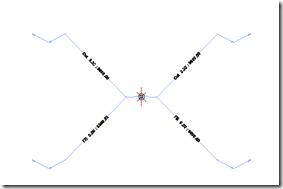
If you look at creating a surface from the featurelines generated by the corridor you see that all the individual linkwidthandslope subassemblies have a point code P2 and thus only one featureline I can choose (this would effectively give me the same result as choosing top links to create my surface).

You need to create unique point codes for each subassembly and thus unique featurelines to choose from for corridor surface.
Select the subassembly and change the Point Code in Properties. Road edge here:

Then slope to rock:

Rebuild the corridor and in now corridor surfaces you should see some extra featurelines:
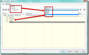
Now on cross sections you should be able to calculate the correct volume for rock fill by comparing this new surface with top of rock:


This includes the portion on the outermost batter. The volume we actually require is this:

To get this we need to create a new surface comprising the road edge featurelines and the featureline where the initial embankment intersects the top of rock. First lets look at my assembly… I am using a combination of generic subassembly (linkwidthandslope) and a conditional subassembly to model different conditions in cut/fill.

If you look at creating a surface from the featurelines generated by the corridor you see that all the individual linkwidthandslope subassemblies have a point code P2 and thus only one featureline I can choose (this would effectively give me the same result as choosing top links to create my surface).

You need to create unique point codes for each subassembly and thus unique featurelines to choose from for corridor surface.
Select the subassembly and change the Point Code in Properties. Road edge here:

Then slope to rock:

Rebuild the corridor and in now corridor surfaces you should see some extra featurelines:

Now on cross sections you should be able to calculate the correct volume for rock fill by comparing this new surface with top of rock:

Subscribe to:
Posts (Atom)