I have been working on a windfarm job recently where the earthworks for the access roads varied depending on whether the design was in cut or fill at a particular location.
In cut the earthworks needs to slope up to meet the existing ground at a 1:1 slope. In fill we needed to slope down to meet the underlying rock layer at a 1:1 slope first and then back up to existing ground at 1:1.
Typically the access road in cross section will slope towards the uphill side of the road and a ditch is placed on this side. See a previous post on a quick method for identifying the uphill side.
Typical road assembly minus earthworks might appear as follows:
For the drainage ditch I am using the Ditch subassembly.
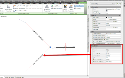
The ConditionalCutFill subassembly will be used to control how the earthworks is applied depending on whether we are in cut or fill. This is located on the Conditional tab of your Tool Palettes.
Looking at the cut situation first we will begin by applying a conditional cut subassembly to the back of the ditch:
Next apply another conditional subassembly to the back of the ditch - this time setting the Type parameter to Fill.

In the Fill situation we want to slope down to rock first at 1:1 - use the LinkSlopeToSurface subassembly again. Set the Add Link In parameter to Fill Only. Attach this to the end of the conditional fill subassembly.
From the rock layer we want to slope back up to existing ground at 1:1. Use LinkSlopeToSurface once more and set the Add Link In parameter to Cut only. Attach this to the end of the link to rock subasembly.
You can mirror all of the earthworks subassemblies to the other side of the assembly to speed things up. Just select the subassemblies you want to mirror and choose Mirror Subassemblies from the ribbon.
The complete assembly will look something like this:
When you are setting targets later in the corridor it is important that you have named each subassembly so that the name identifies what surface you will be targetting. e.g. Cut to Rock Left 1:1.
Create your corridor and set the targets in the corridor properties as required - see screen grab below for an example of how they might look.
Create your corridor and set the targets in the corridor properties as required - see screen grab below for an example of how they might look.
Now we have our various earthworks conditions being controlled automatically by one assembly. Should changes be made to the vertical design of the roads later, the cut/fill conditions on the conditional subassemblies will look after any changes to the earthworks for us. See sample of what the resulting sections look like below: (existing ground - green; top of rock - magenta; road surface - red)
Cut Situation:
If you are looking to explore the conditional cut and fill subassemblies a bit further I would recommend working through the example at the following link:


Good post - I use conditionals for this work all the time but I tend to target the rock/competent material surface only rather than EGL (i.e. In your example - Fill Situation Right side - would you not also have to excavate the material on the left side to rock level i.e. the road trapezoidal shape would be founded exclusively on rock??
ReplyDeletePS not trying to disparage your post in any way but keen to understand how others go about this type of work
Hi Neil,
ReplyDeleteThanks for the comment. On this job there was also a peat layer which was stripped from the site. I haven't mentioned it or shown it on the sections for clarity. (Intention was to show the functionality of the conditional cut/fill).
There was an intermediary layer between the peat and rock that was deemed competent to build on and that was what was done in this case.
Thanks for the clarification
ReplyDeleteSimply stated. Well explained.
ReplyDeleteSample CV Template